design
For this next project, I decided to continue working with the same concept as the previous week. For a review of the "whirlibird" idea, you can check out my previous post: analog 3D model.
This week, my goal was to create a model of the whirlibird concept using 3D CAD software. Prior to class, I went through some basic instructional videos to learn to use the modeling tools in Onshape, an impressive web-based product development platform. In high school, I'd used Autodesk Inventor quite a bit in various engineering courses, and I'd tinkered with Fusion 360 very casually since then, but it had been a while since I had tried using any CAD software seriously, so I was excited for the chance to brush up these skills.
Since our course is entirely remote this quarter, we unfortunately don't have access to the on-campus maker space to 3D print our models. However, this was still a great opportunity to practice using CAD, and the digital model could be used to evaluate the feasibility and aesthetics of the form for the product.
prototype
I began by modeling the base shape of the hat. This was fairly straightforward, as I revolved a series of ellipses to create the uniform round shape. In an effort to make it at least a little bit realistic, I cut out a hole in the top of the hat where a motor might be mounted, and also modeled a basic motor shape to fit in this cutout. As with the hat, I sketched the profile of the motor and revolved it around the center axis.
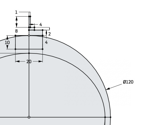
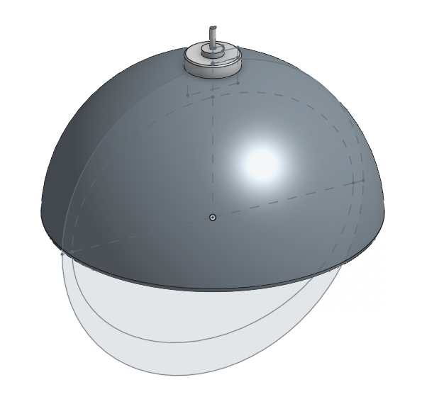
The sketch of the hat and motor, then the parts after revolving
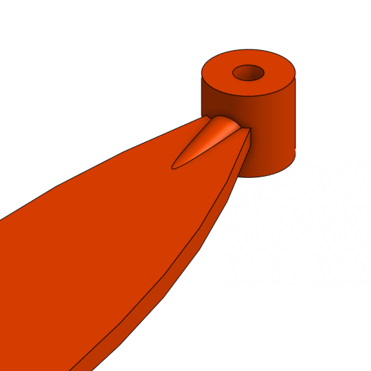
The propellor that should go on top of the hat proved much more difficult. For simplicity, I decided not to try to model the bone shape that I created last week—though I haven't forgotten about it! The biggest snag that I hit was that I wanted the blades of the fan to be flat, but on my first attempt, they didn't sit flat. Normally, fan blades should be at an angle, but in my case, the blades aren't meant to generate lift or move air, so they should be flat.
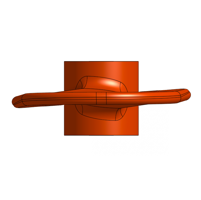
In the front view of this fan blade, notice that the sides of the blade tilt up or down slightly.
I couldn't help but think that if I had wanted my fan blades to be at an angle, I would have had far more trouble. It turned out to be a relatively simple problem, though: to create the blade, I had used an operation called a loft, which forms a smooth 3D solid from multiple planar sections. In order to create the solid properly, the software must figure out how to match the points between the different sketches. Incorrect matching of these points often leads to a twisting shape, which is what I was experiencing. I was lofting from a circle to a rectangle, and Onshape was trying to figure out how to match up the points between the different shapes (and getting it slightly wrong).
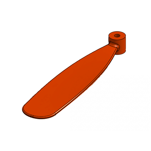
I ended up switching the circle shape to also be a rectangle to solve this problem, since I couldn't figure out how to make the points match up correctly. In order to add the additional support between the blade and the cylindrical base that I had been going for, I added an additional circular loft on top of the original part.
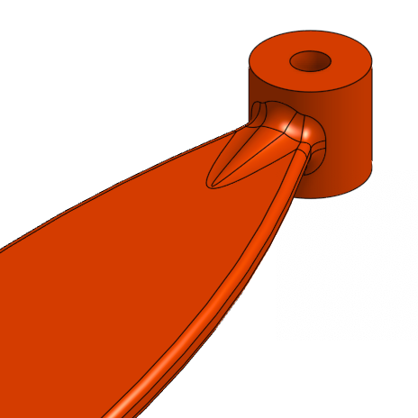
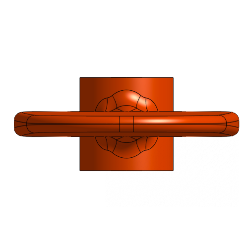
The revised blade, before and after smoothing ("filleting") the edges, and a view from the front
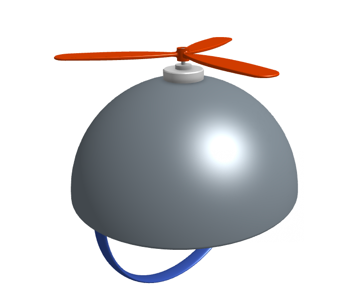
I also added a chin strap to the hat—we'll explore the chin strap more next week!—and then I was ready to put all the pieces together.
I created an assembly and dropped all the components in place. In an assembly, you can create "mates," or different kinds of relationships between different parts. In particular, using a cylindrical mate between the propellor attachment and the shaft of the motor allows you to rotate the blades as they would with a physical propellor.

analysis
I had a lot of fun getting back into CAD and make something cool! I think the model turned out quite well and spinning the fan blades around is way too much fun. I think there's a lot of opportunities to do more here, though I don't have time to explore the full range of what the software offers.
If I were to do this process over again, I would want to do more (faster!) iterations and just explore more! This week, I started with an idea of what I wanted to build in my head, and I generally stuck to that throughout the process, without deviating too much. One thing that I noticed was that the set of things possible to create in Onshape (at my skill level, at least) is definitely very different than the set of things possible for me to make last week out of real materials (again, at my skill levels and with the limitations of the materials and tools I have). The ability to explore new forms that might not have been possible before is an interesting benefit of the modeling software that I think I could benefit from taking advantage of this.